Battery Type/'s
-Lithium 100AH Batteries with 3.3KW Charger-Lithium 200AH Batteries with 3.3KW Charger
-Lithium 100AH Batteries with 6.6KW Charger
-Lithium 200AH Batteries with 6.6KW Charger
Installing charger
The new charger mounts in relatively the same location. For non-air conditioner vehicles, the charger mounts as shown in these images:
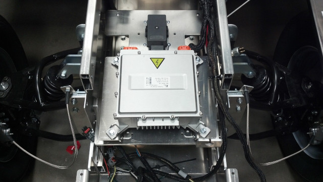
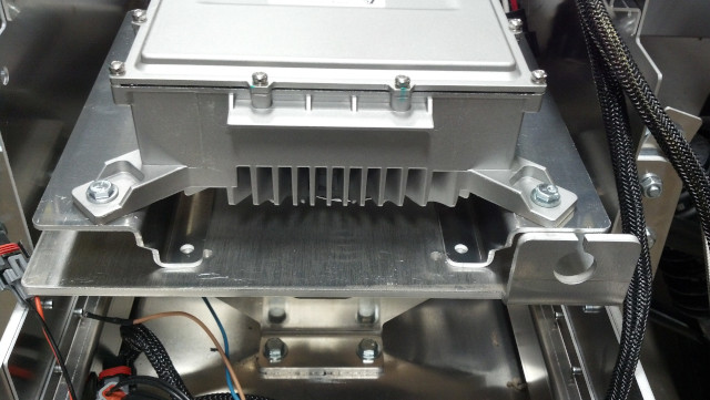
For air conditioner vehicles, the charger mounts as shown in this image:
Note all wiring is setup for rear mounting. Cut wire to desired length when mounting charger in front.
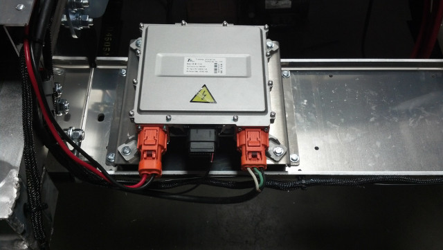
Larger black wire is the battery negative and will but splice to existing black wire going to the old charger. If old charger has a connector this wire would be white. As an alternative this can be attached to the switched side of the disconnect switch.
The larger red wire is for the battery pack positive and will but splice to existing red wire going to the old charger. If old charger has an existing inline connector, it can be cut off and removed.
The three 12ga wires (red, black and green) are the AC input wires. These splice to the same colored wires. If old charger has an existing inline connector, it can be cut off and removed. Splice wires with matching colors.
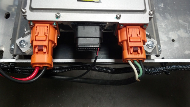
The small wires with the gray sheathing are for CANBUS. If vehicle was built prior to 2023 you will need to wire the CANBUS differently. Currently it is wired to the high voltage side of the CANBUS. You need to change it to the low voltage side of the CANBUS. This is very important. If not done so you have high risk of speed controller, charger, dash display and isolator failing. In order to change this the CANBUS wire supplied with new charger needs to be run to the wires going to the diagnostic port.
At the diagnostic port you will find the same gray cable. You will be doing an inline splice into the cable wires. So existing cable wiring will remain. When splice is complete you will have 2 red wires on one side of splice and one red on the other. You will have 2 black wires on one side of splice and one black on the other. The bare wire does not go to the diagnostic port but take and splice bare of new cable to bare of cable going to diagnostic port.
This next step only pertains to vehicles equipped with air conditioning. All CANBUS systems need 60-Ohm resistance. This is performed by a single 120-ohm resistor on each end of the CANBUS system. The vehicle has two CANBUS systems. A low side and a high side. You will want to inspect the wiring at the charger and at the diagnostic port. If you find an electrical component connecting the red and black wires together this would be the 120-ohm resistor. At the diagnostic port it will be right at the rear of the terminals going into the port. At the battery charger it will be at the black connector were the back of the terminals get inserted into the connector. If both locations have a resistor you will want to remove the resistor at the diagnostic port.
Next you need to check the high voltage CANBUS side. Go to the 35-pin connector plugged into the speed controller mounted at the passenger's side rear inner fender. You access it by going under the vehicle in the rear. Speed controller is the large black box with battery cables going to it from the drive motor. The 35-pin connector has a retainer on its inner side. Release it and unplug connector. At the rear of the connector the 4 corners are marked with numbers. These are the pin locations. Find pin #'s 21 and 34. If you have a black short black wire jumping between these two pins repair is complete. If you do not have this jumper wire you need to insert the short black wire that came with KIT-50. To do so the red cap of the connector needs to be snapped up one click. Try you best not to completely remove it. Then slide the black jumper wire into pin# 21 and other end to pin# 34. When fully seated terminal will snap into place and not come back out easily. After both terminals are seated the red cap can be snapped back down. If it will not slap back down the terminals are not seated correctly.
Turn main battery disconnect switch back on and if equipped with lithium batteries plug the vehicle in to charger for at least 3 seconds to get the vehicle to power up.
Test to see if everything is working correctly making sure the speed registers on the display also on the up button of dash display, take and press and hold it until second screen comes up. All the values should read a number. If all values are 0 then there is an issue with the installation.
The Final step is to re-install the components back together in reverse of how it was taken apart.